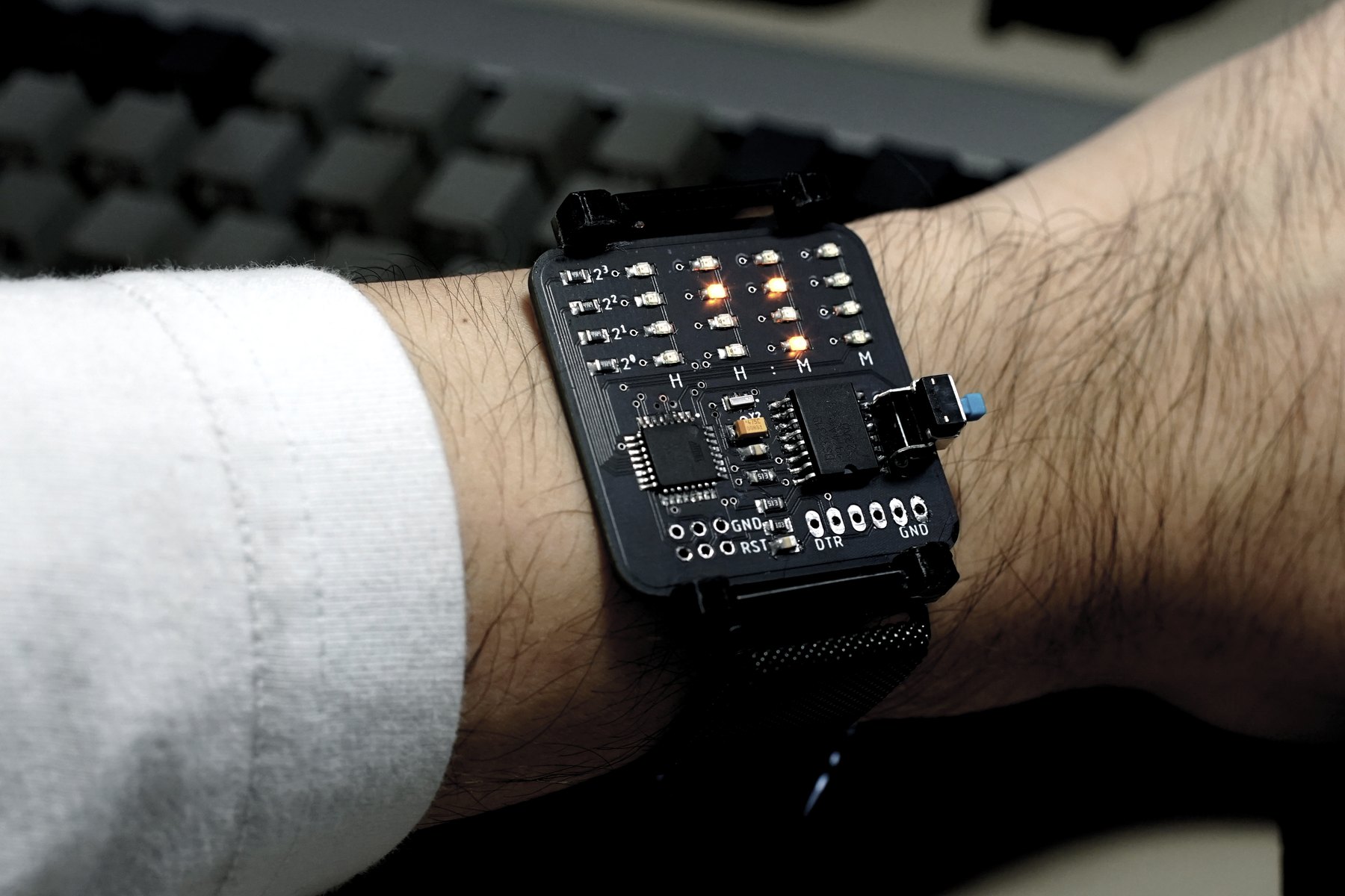
𝍄 BinWatch
A naked-PCB wristwatch that displays time and date in binary on a 4 by 4 LED matrix.
Overview
PCB as the product
BinWatch is a fully functional electronic wristwatch that displays time and date in binary. Rather than hiding the electronics inside a conventional enclosure, I designed the circuit board, components, traces, and mounting hardware to become the product itself.
The design uses an ATmega328P-AU microcontroller, a DS3231 real-time clock, a 4 by 4 LED matrix, and a single CR2032 coin cell. A side-mounted button wakes the display and cycles through the available information, keeping the interface simple while limiting unnecessary power use.
The exposed PCB gives the watch its visual identity and keeps the profile thin while introducing stricter constraints around size, power, assembly, and comfort.
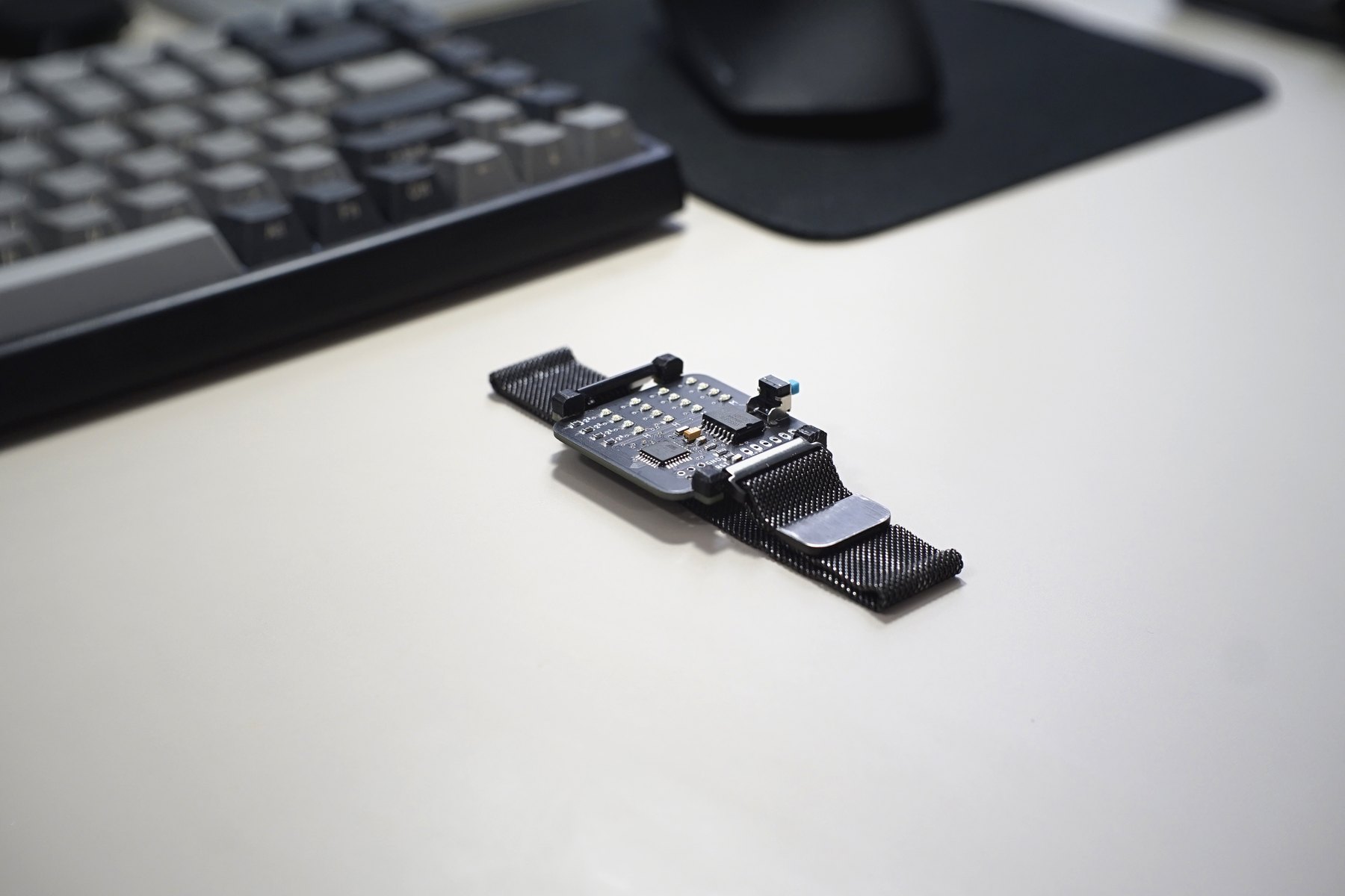
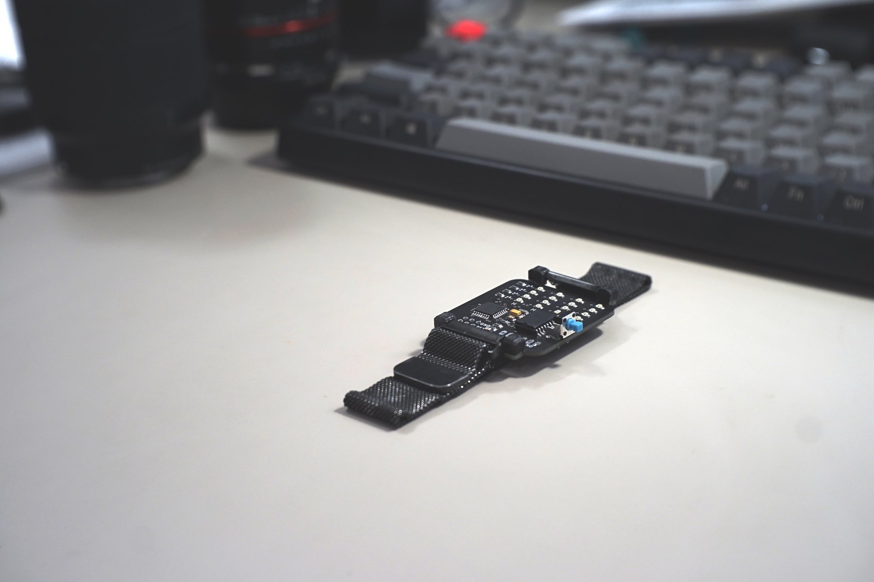
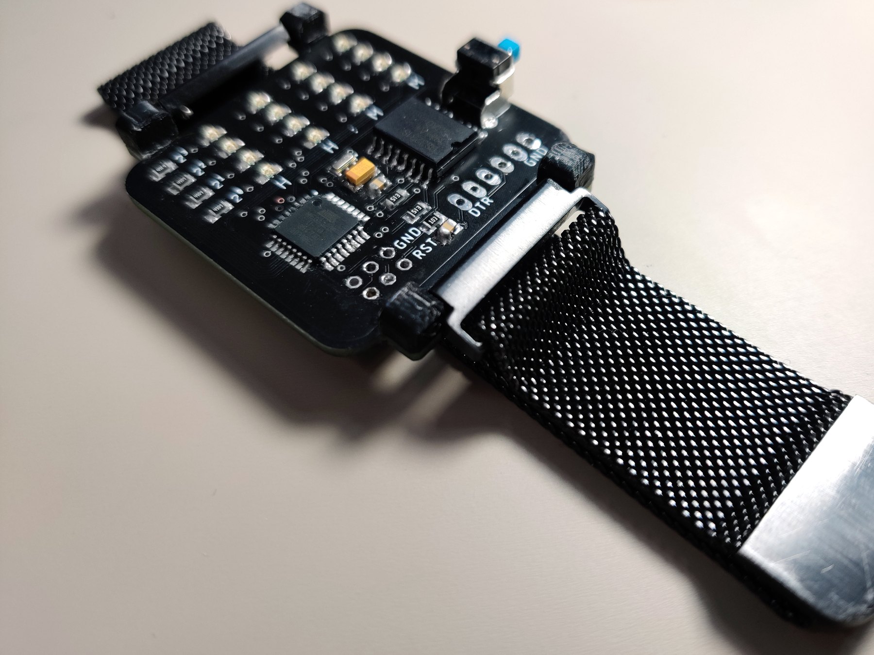
The final watch
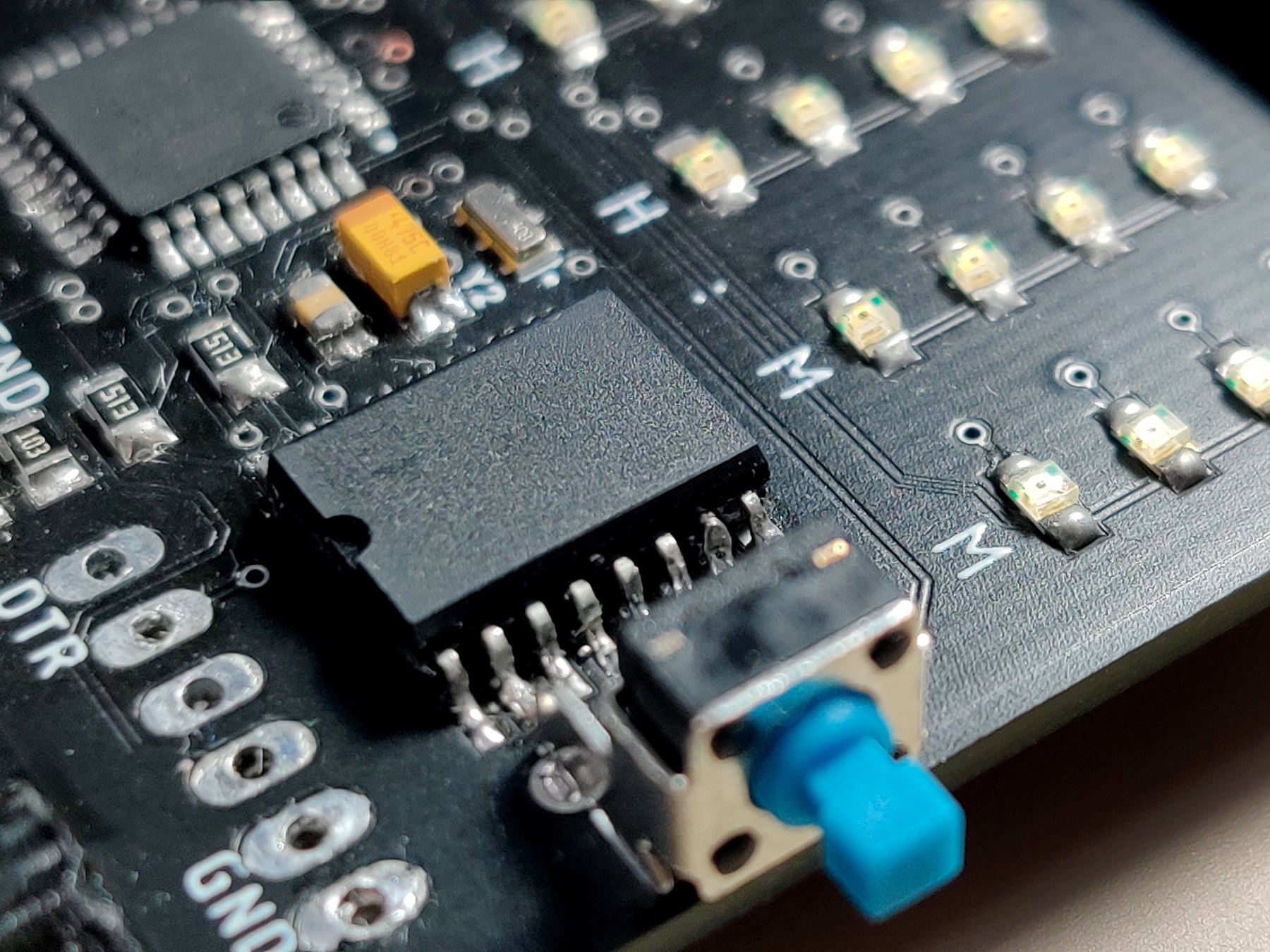
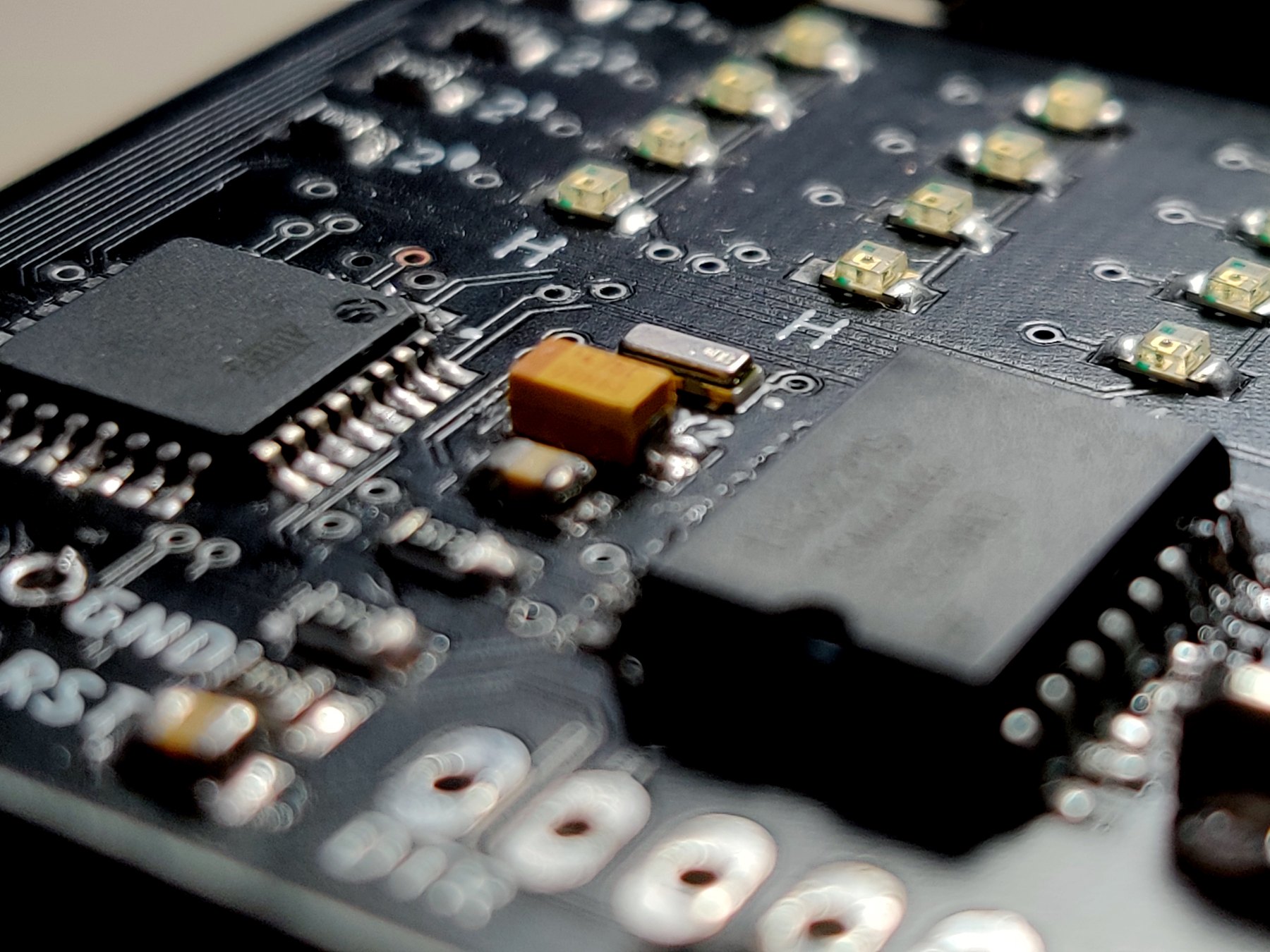
Design lineage: Printed Business Card
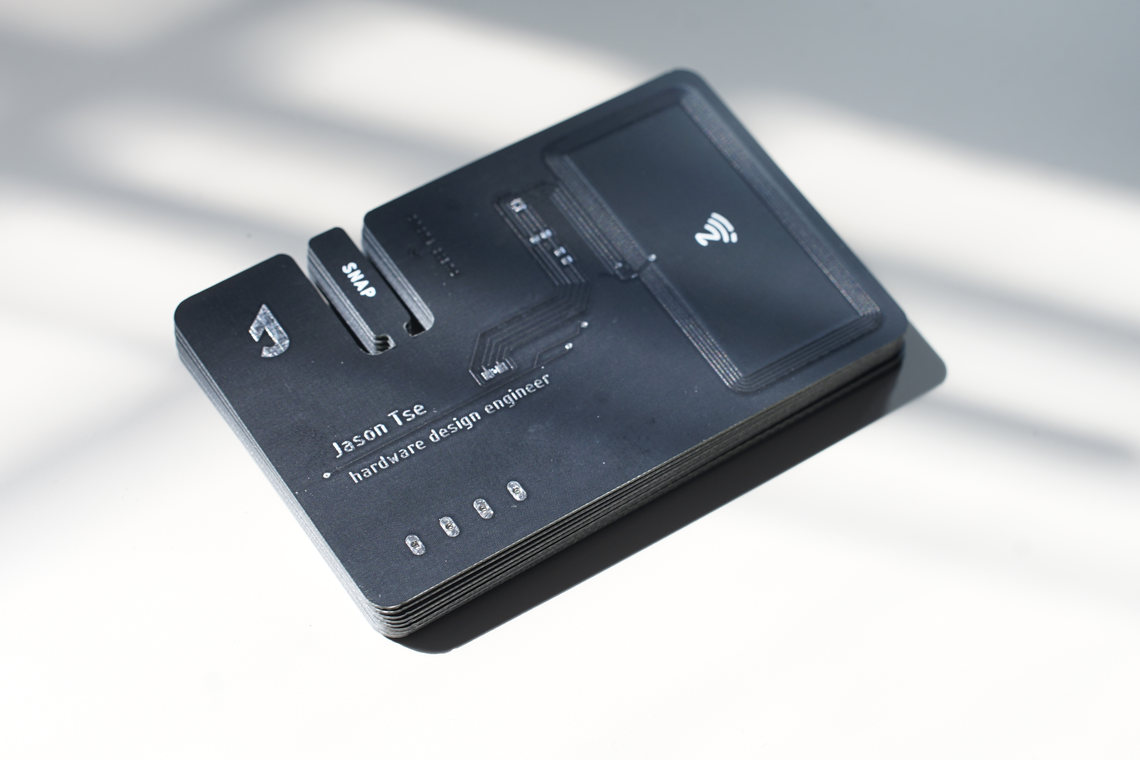
I became interested in PCB design after building my first, unsuccessful board for Deqing Sun’s Prototyping Electronic Devices class. The failure made the discipline compelling: a working board depends on the circuit, component selection, footprints, routing, fabrication, and physical design all agreeing with one another.
My earlier Printed Business Card (PBC) then explored an NFC-powered business card as a finished, enclosure-free PCB product. BinWatch carries that same “PCB as product” design language into a wearable device with new constraints around power, comfort, interaction, and mechanical attachment.
Inspiration
Make reading time deliberate
For a project in the Time class, I wanted to build something more playful than a conventional digital or analog watch. A binary clock turns a quick glance into a small decoding exercise. Each illuminated LED represents a binary value, and the values in each column combine to form the decimal digits for hours and minutes.
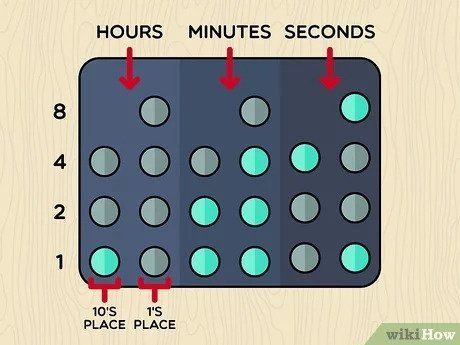
In the example above, the hour columns resolve to 10 and the minute columns resolve to 37. BinWatch adapts that familiar binary-clock pattern to a compact wristwatch, expressed through my own circuit and PCB layout.
Design and engineering decisions
As the design became smaller, the visual and technical decisions became inseparable. Every added component affected board area and power draw; every physical choice constrained routing and assembly. Once the PCB was manufactured, there would be little room for improvisation.
Microcontroller and real-time clock
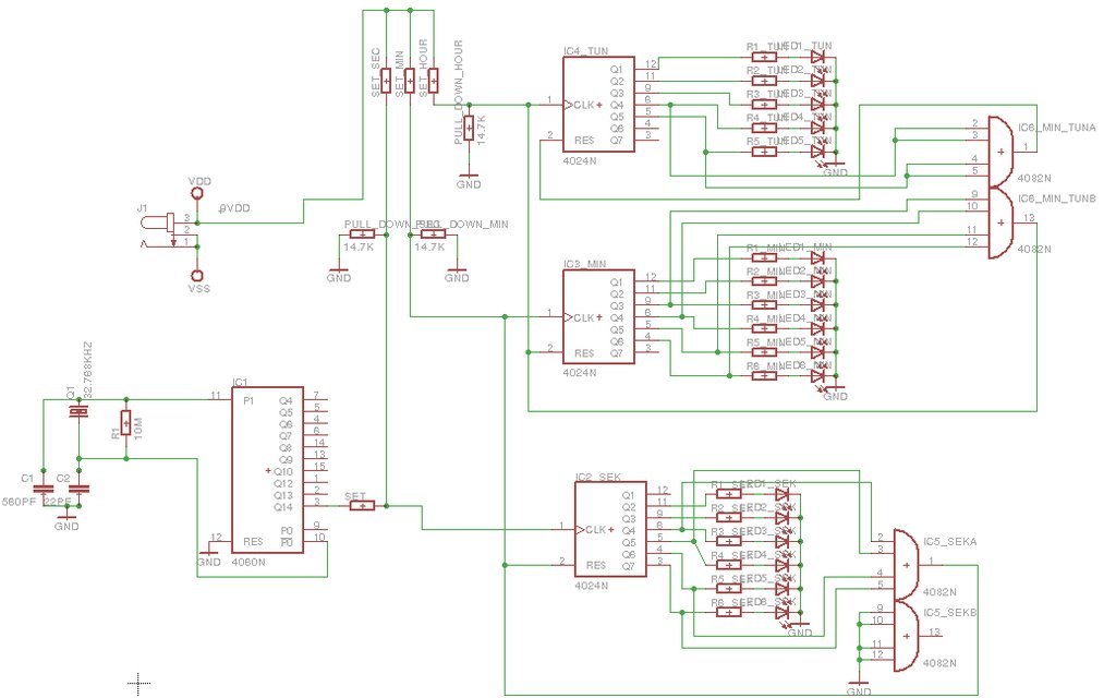
I considered building the clock from counters and a 32.768 kHz crystal. That approach was appealingly direct, but it required more components, more board area, and a more difficult path for adding interactions later.
I instead chose the ATmega328P-AU, the surface-mount microcontroller used in compact Arduino-compatible boards. It let me reuse a familiar toolchain and implement the watch behavior in software. A DS3231 RTC handles accurate timekeeping and provides calendar data without asking the microcontroller to maintain time continuously.
Battery, LEDs, and interface
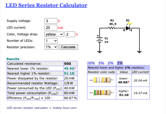
A rechargeable LiPo would have required charging and protection circuitry, adding both complexity and volume. I chose a replaceable 3 V CR2032 coin cell and designed around low current consumption instead.
Yellow LEDs balanced visibility, color, and power use. The watch uses one physical button as its only interface: the display remains off until the user asks for information. Software provides the interaction without adding more power-hungry hardware.
Final specification
- Custom, enclosure-free PCB sized for a standard 20 mm watch band
- ATmega328P-AU running with an 8 MHz resonator
- DS3231 real-time clock with calendar support
- 4 by 4 yellow LED matrix
- Single side-mounted input button
- CR2032 coin-cell power
- ICSP and serial programming interfaces
- Board fabrication in China, with components sourced and hand-soldered in Brooklyn
Schematic and board design
The schematic centers on the ATmega328P-AU and DS3231, with the LED matrix, resonator, button, battery, and programming interfaces arranged around them. I included dedicated ICSP and serial connections after learning, on an earlier PCB, how fragile direct wires soldered to microcontroller pins can be.
Before routing the board, I reviewed the schematic repeatedly. A schematic error would propagate directly into the manufactured hardware.
Component footprints became part of the industrial design. Standard surface-mount packages were predictable, but the side button and battery holder varied considerably between suppliers. I checked footprints and 3D models against actual Digi-Key availability before committing to a part. I also maintained the bill of materials while designing, rather than discovering availability and cost problems after the layout was complete.
From circuit to PCB
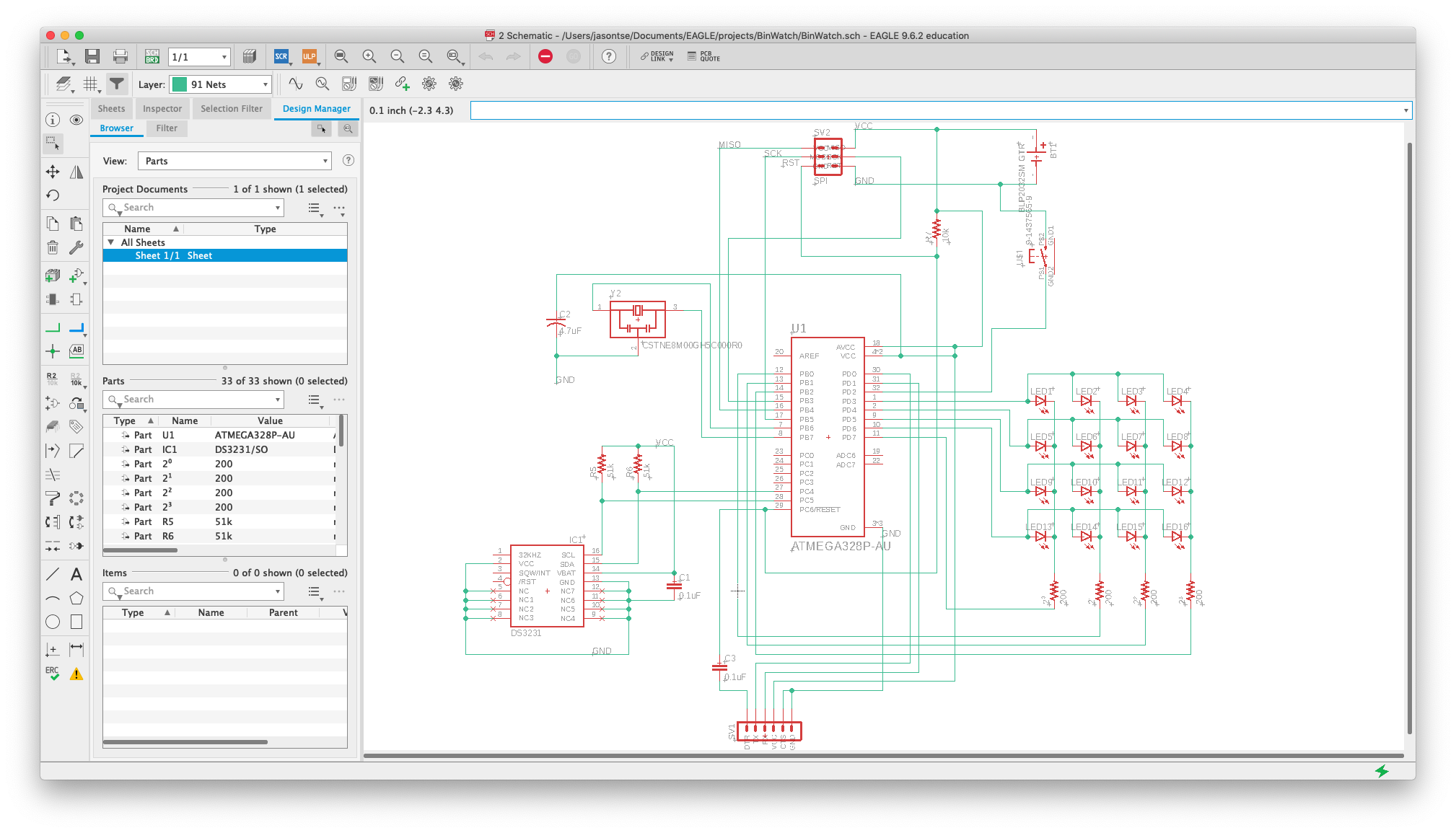
Schematic
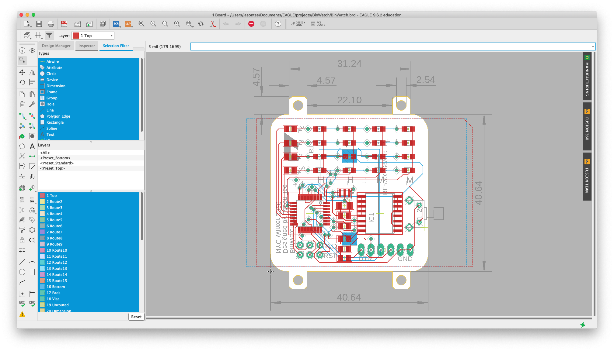
Board layout

Footprint research
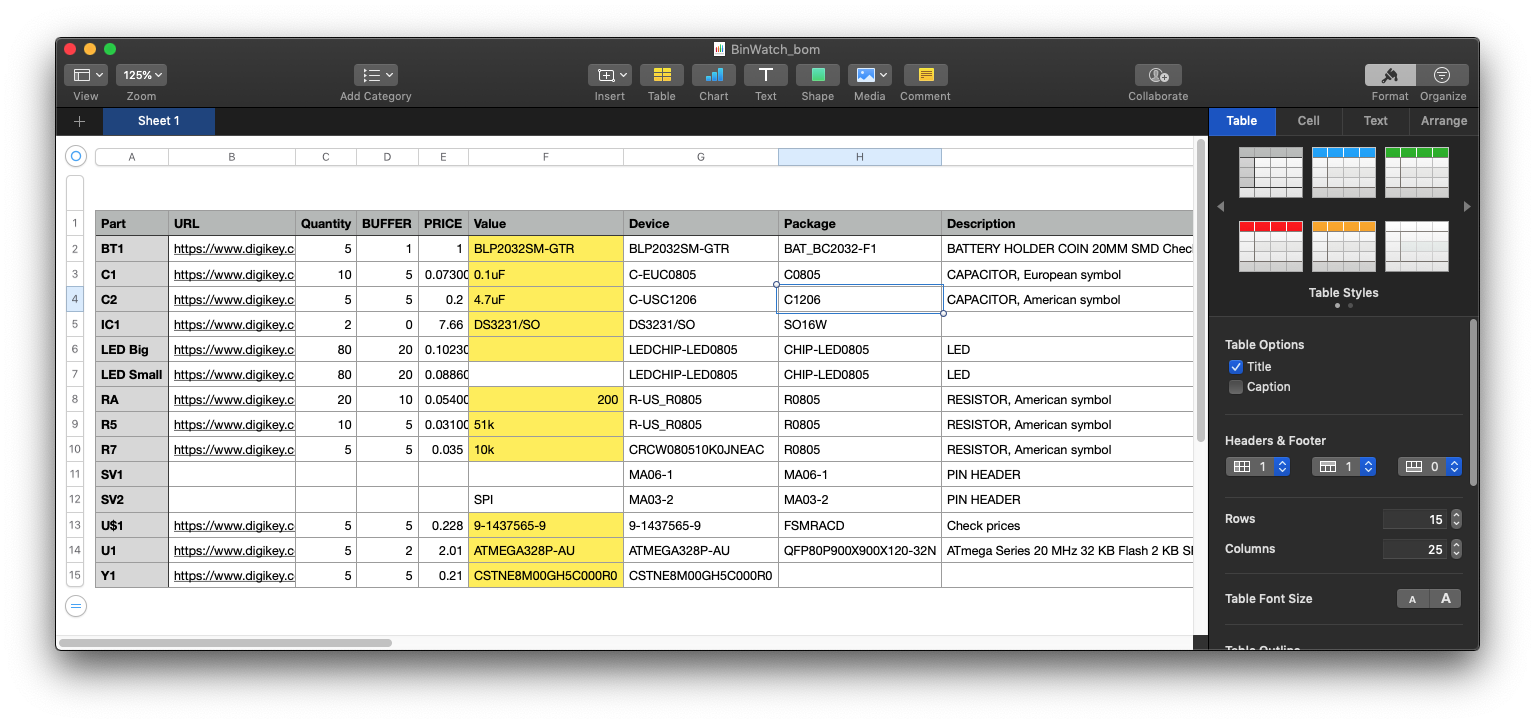
Bill of materials
Parts, testing, and soldering
With custom boards, spare parts are not optional. A damaged pad or overheated component can stop the entire build, so I ordered multiple PCBs and extra quantities of the small components most likely to be lost or damaged.
That caution proved worthwhile. Despite working carefully, I ruined the first board and microcontroller with excess solder and pressure on the pins. The next attempt benefited from that failure: I tested components in stages, controlled the amount of solder more carefully, and verified the board before moving on.
Assembly process
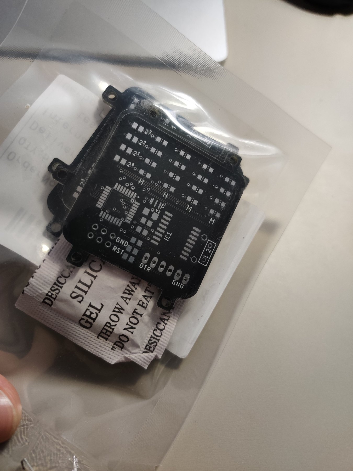
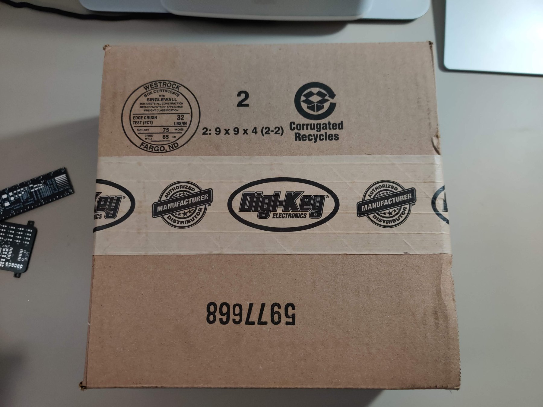
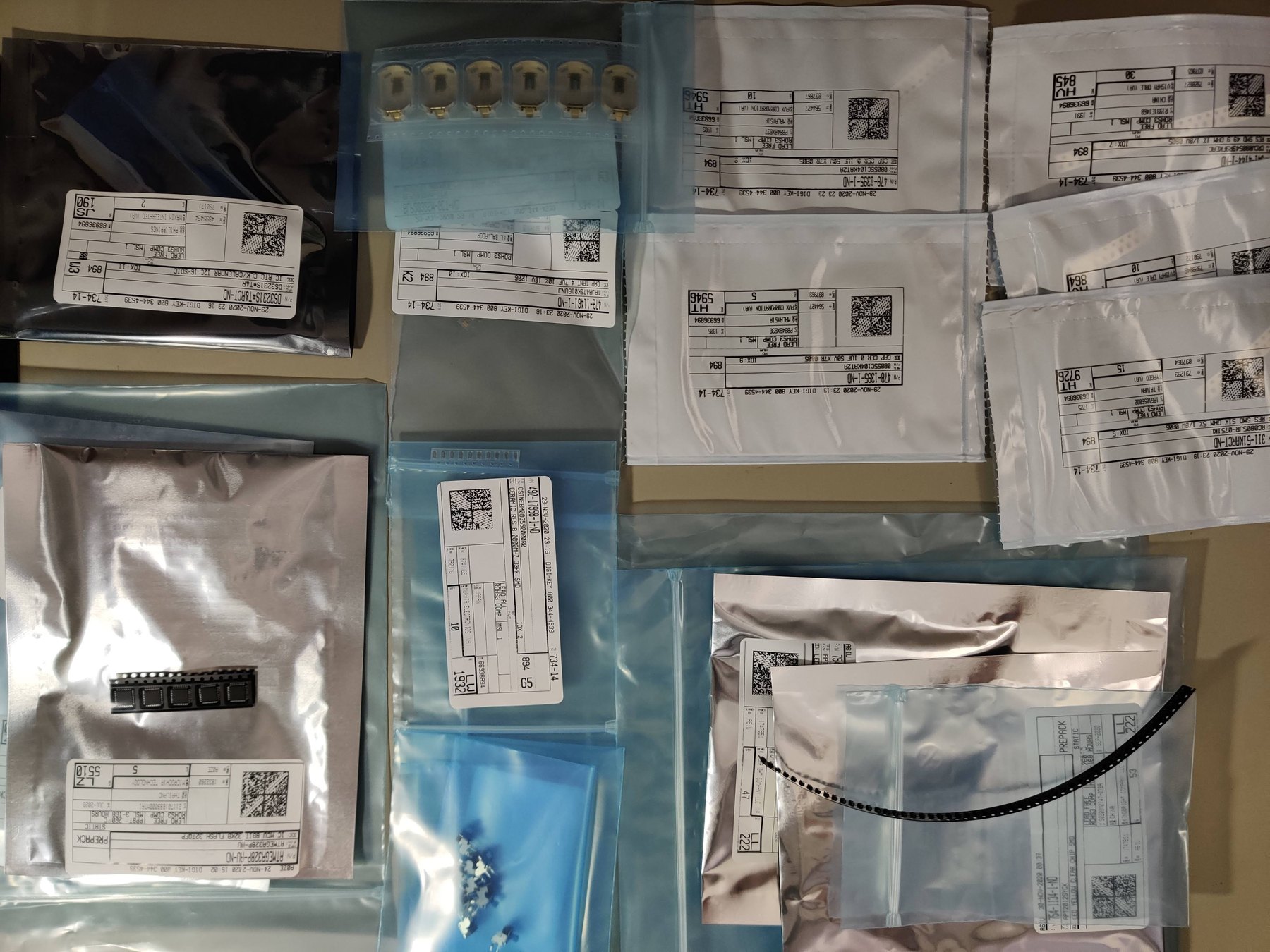
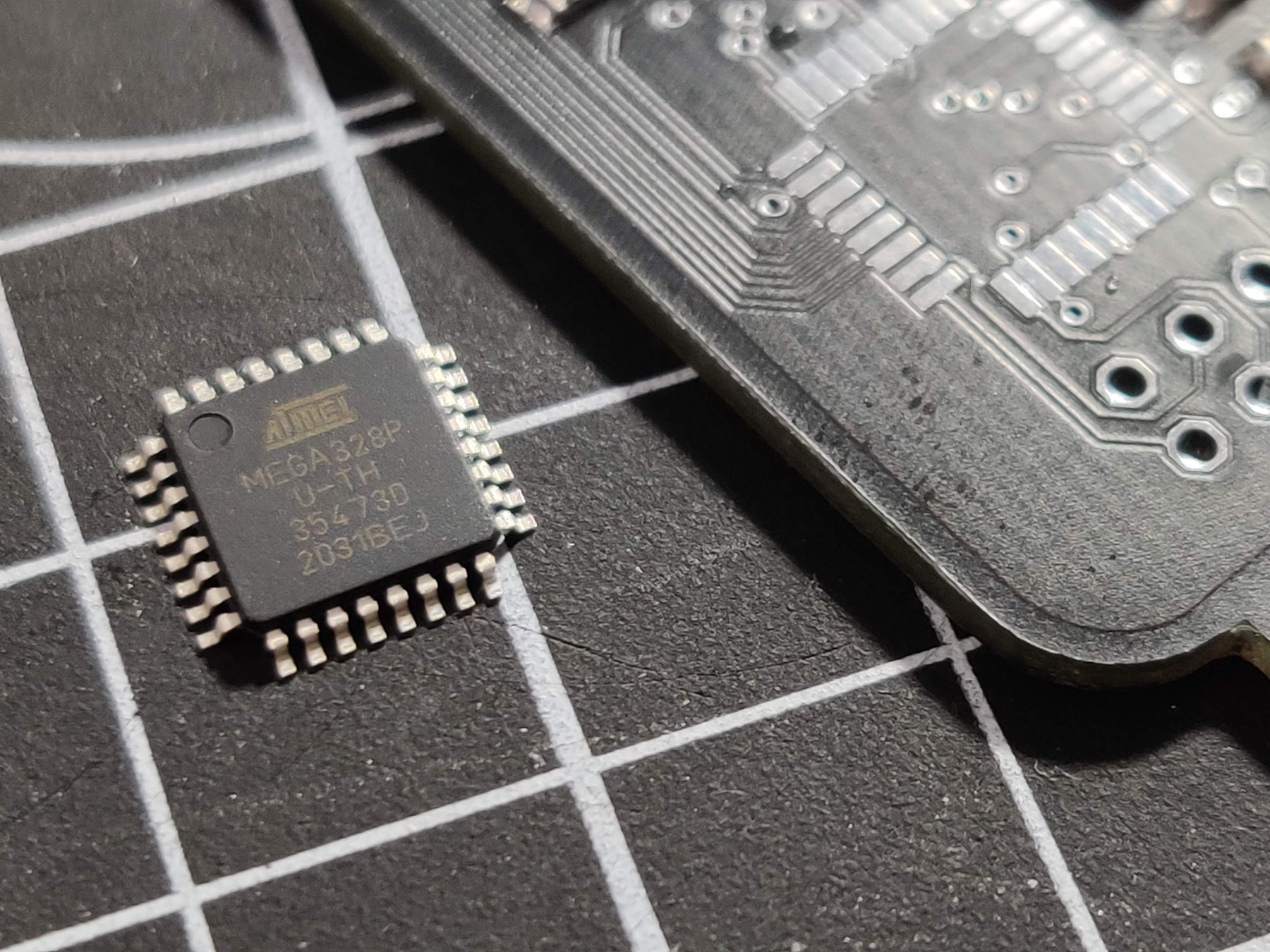
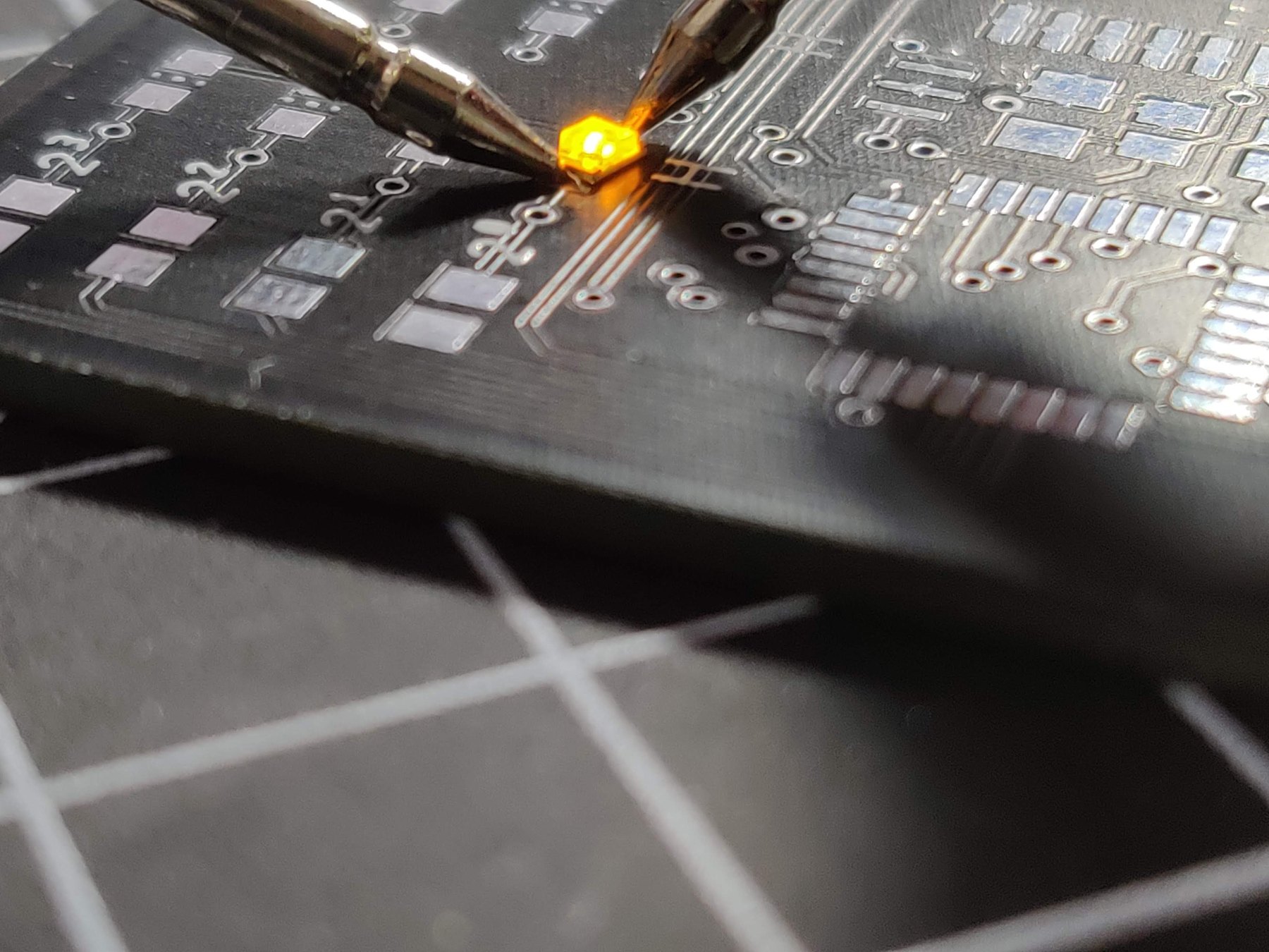
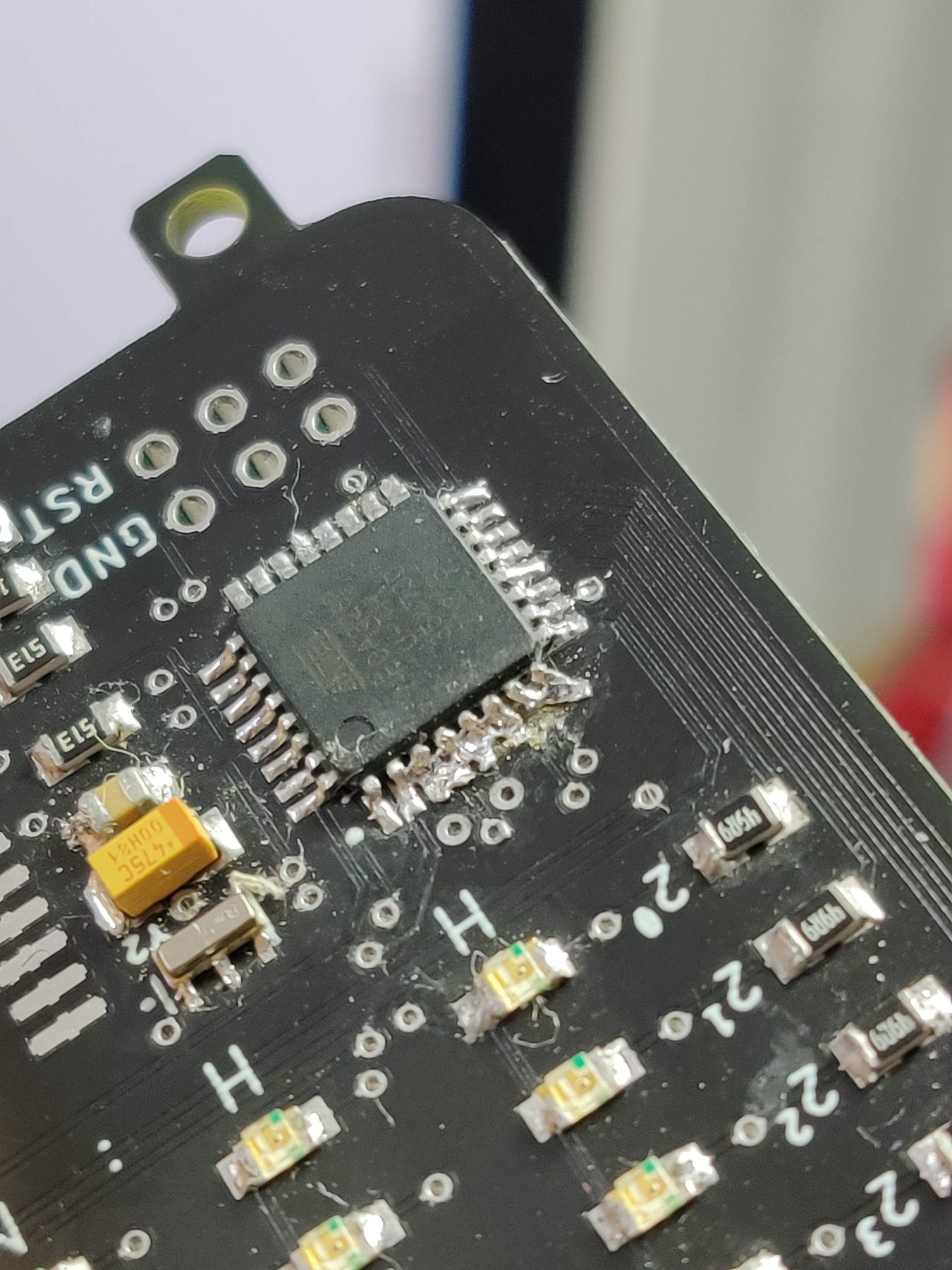
Assembly tests
Bootloader and programming
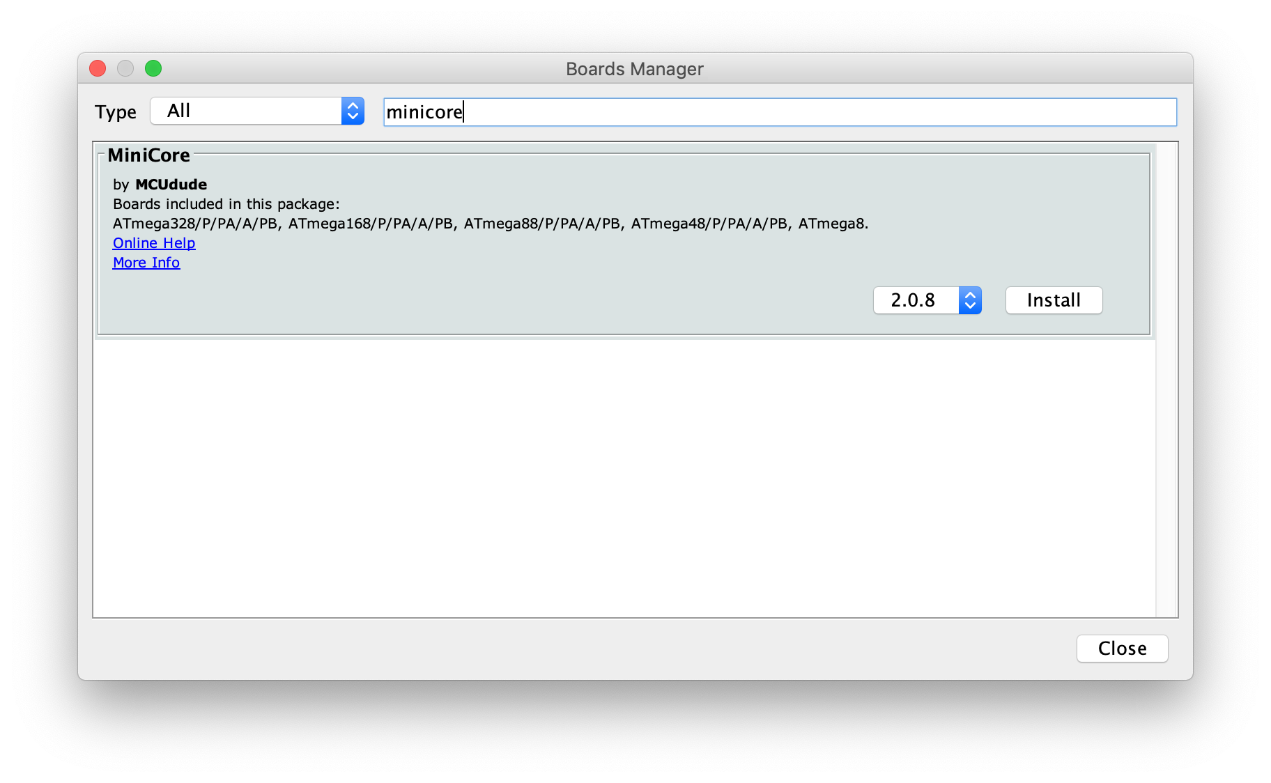
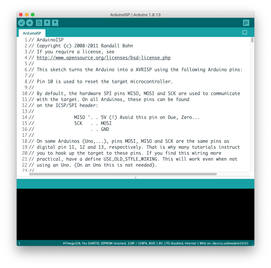
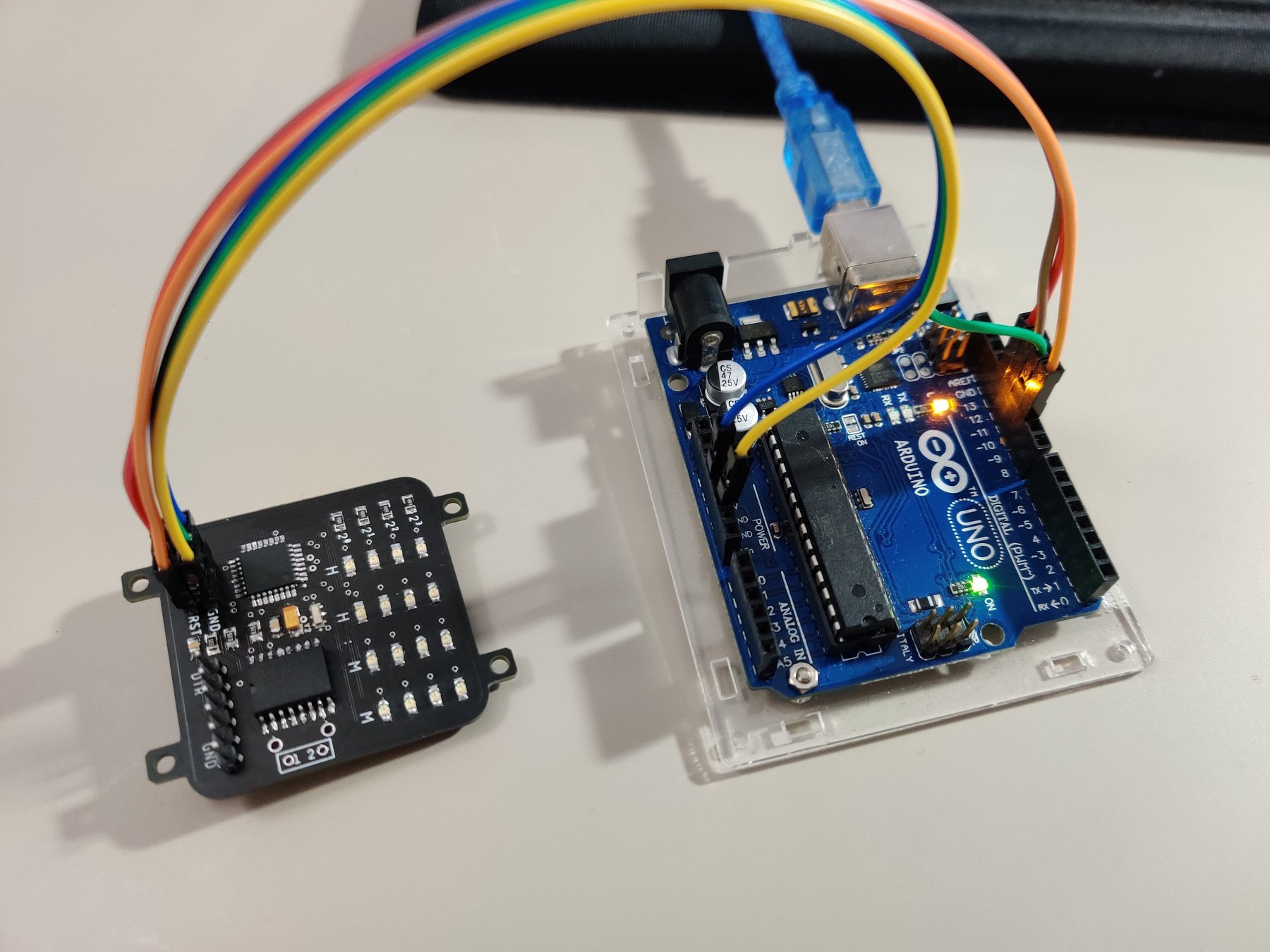
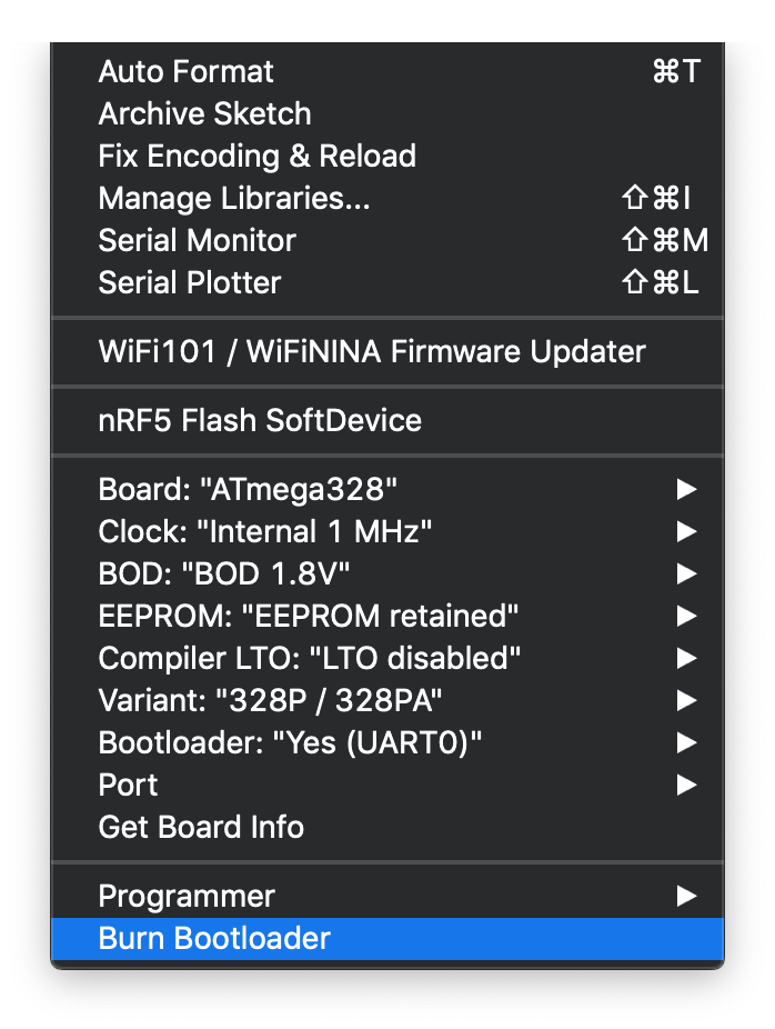
Before uploading the watch firmware, the empty ATmega328P-AU needed a bootloader. I used MiniCore, which supports configurable clock speeds and allowed the microcontroller to run at a lower frequency for reduced power consumption. An Arduino, configured as an in-system programmer, burned the bootloader onto the watch.
The PCB’s USB serial pins did not work reliably with the FTDI programmer. I therefore continued programming through the Arduino-as-ISP connection. Uploading this way erased the bootloader each time, but it gave me a dependable route for iterating on the firmware and finishing the watch.
Programming workflow
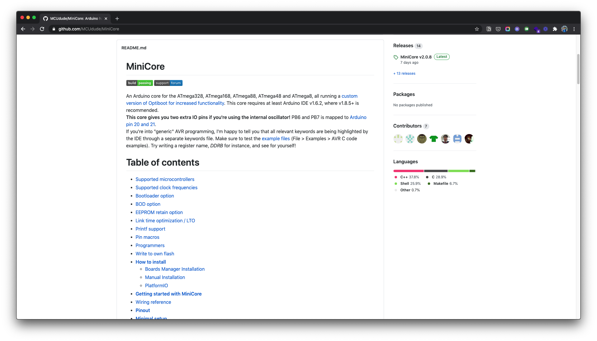
MiniCore configuration
Arduino as ISP
Watch firmware
Programming fixture
Programmer setup
Watch-band bracket
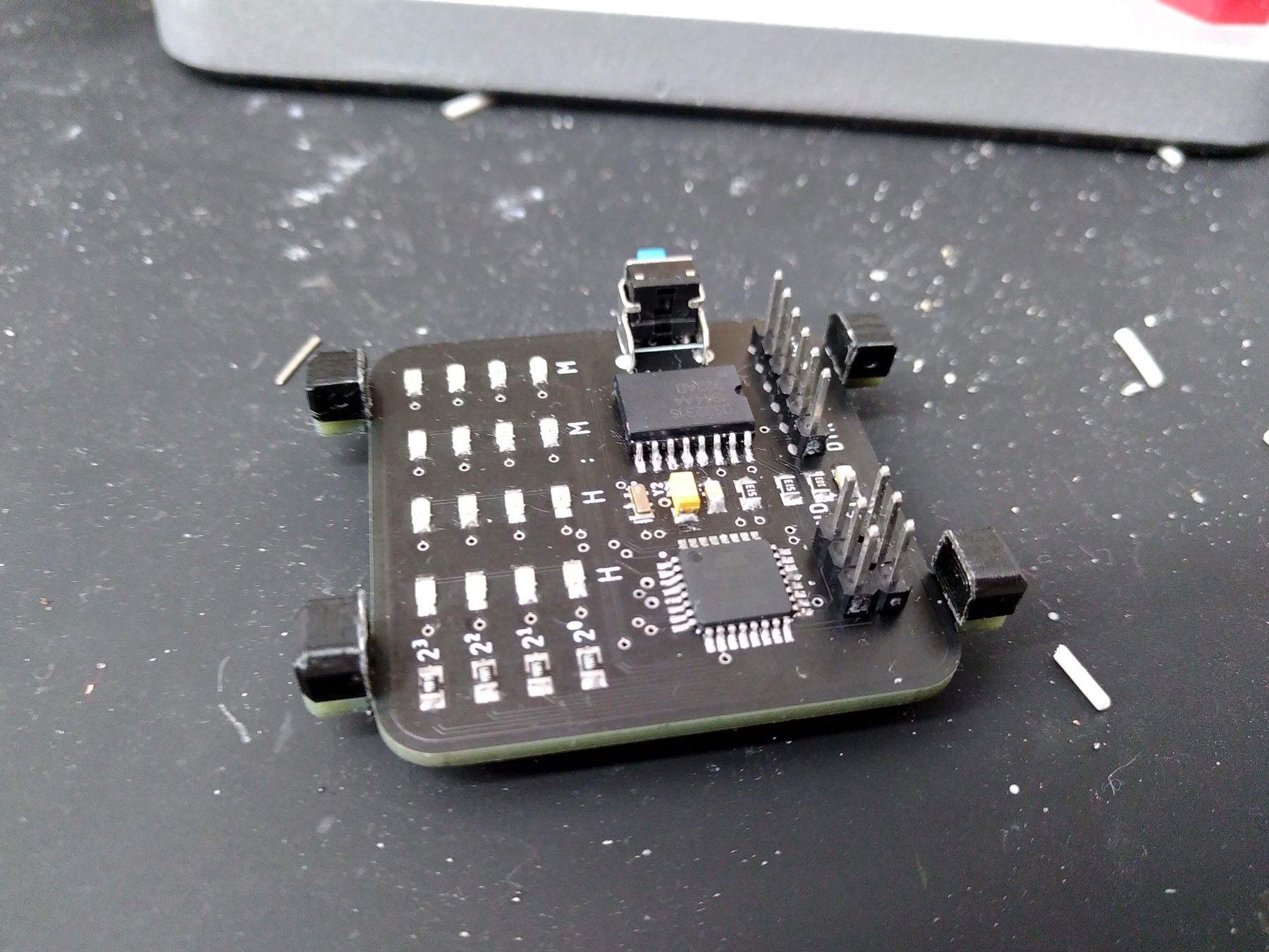
I placed mounting holes slightly more than 20 mm apart while laying out the PCB. After fabrication, I transferred the board geometry from Eagle into Fusion 360 and designed a small bracket around those mounting points. The printed bracket connects the exposed circuit board to a standard 20 mm watch band without requiring a conventional enclosure.
Bracket development
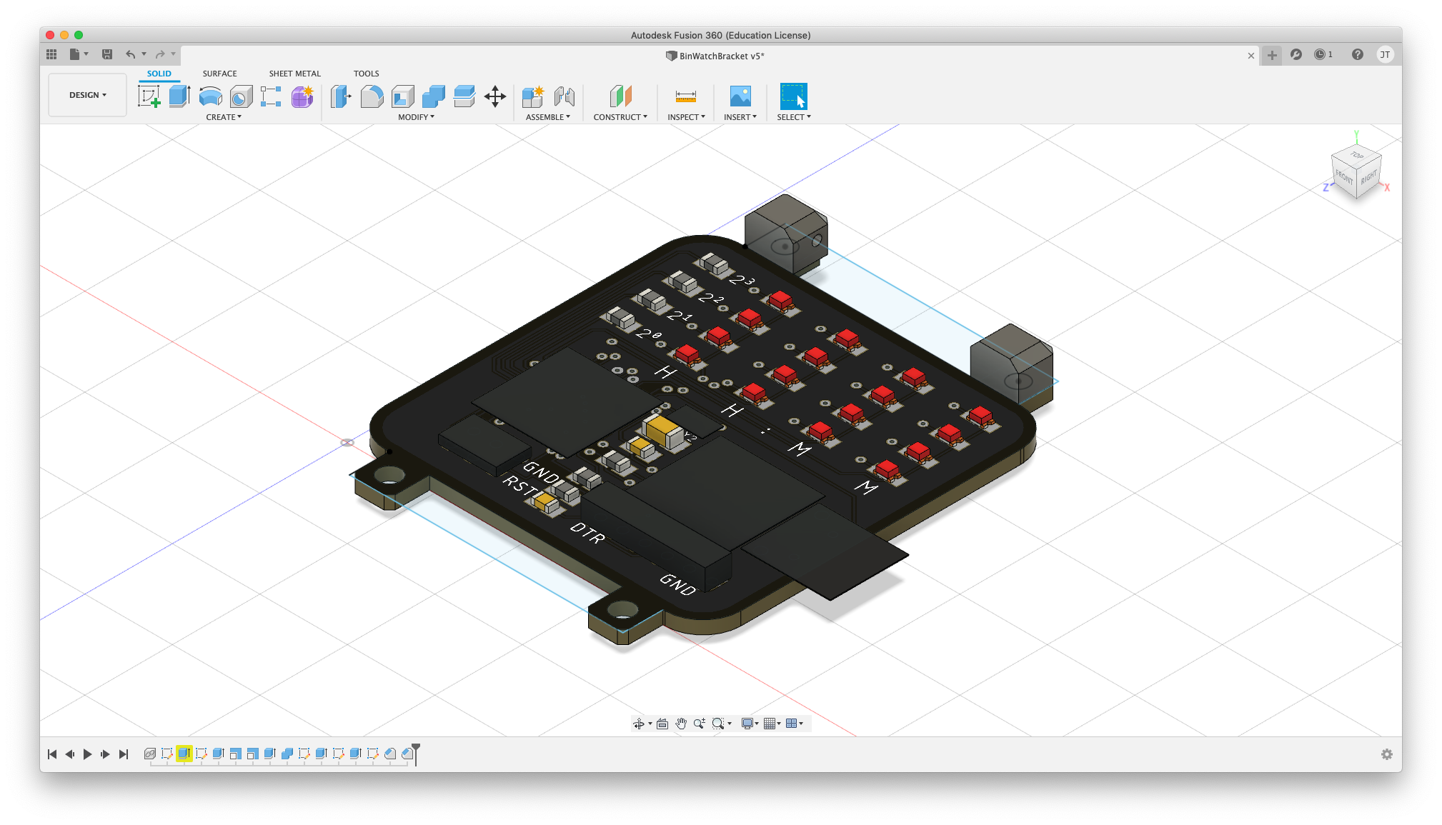
Fusion 360 assembly
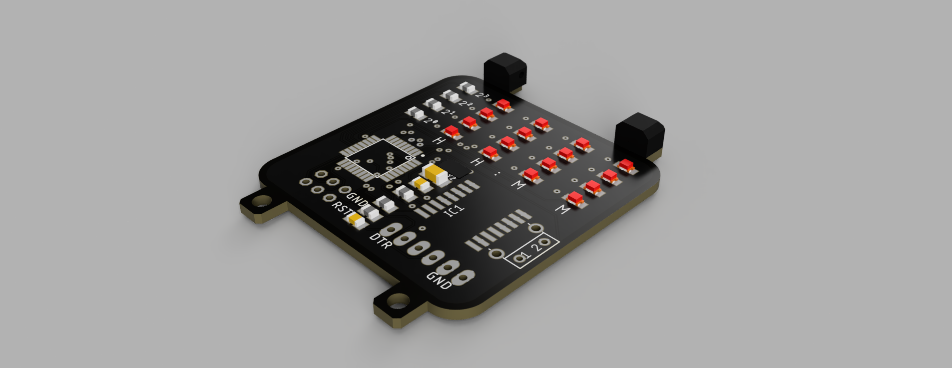
Bracket render
Result
BinWatch became both a wearable clock and an exercise in designing across electrical, software, mechanical, and visual constraints. The failures were as useful as the finished board: they changed how I verify schematics, choose footprints, order spares, expose programming interfaces, and plan for assembly before sending a PCB to fabrication.
The finished watch was later featured by JLCPCB on Instagram. The original long-form build notes remain available in the 2020 WordPress archive.